Hello friends!!! Welcome to the second part of the communication tutorial. In this tutorial we will be reading about USART protocol, which is widely used for data transfer in microcontrollers. Before going into configuration of USART in microcontrollers, let’s first understand what this USART is??
“USART- Universal Synchronous Asynchronous Receiver Transmitter “as the name suggests, it is capable of both Synchronous and Asynchronous mode of data transfer. In this tutorial, we will be dealing with the Asynchronous mode, which sends one frame at a time. Don’t worry, you will very soon understand what this means.
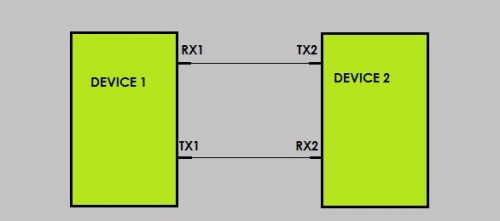
First of all, USART in Asynchronous mode is a full-duplex type of communication, i.e., there are two data lines. It must be very clear from the picture that for the data to be transferred from device 1 to device 2, the data must go through pin TX1 to RX2 serially.
After understanding this point, you must be having a question in your mind, how the device2 does come to know when data is sent??
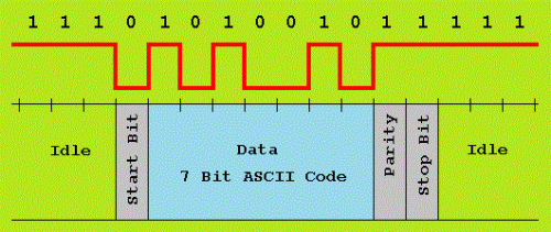
The answer is quite simple indeed. As there is no clock present that denotes the onset of data, there has to be some kind of indication in data line that will indicate the start of data and end of data. These are called “START bits” and “STOP bits”. The start bits can be thought of as a marker that says to the device “Here comes the data!!!” and stop bit as a marker that says to the device” That’s all Data for now…Be prepared for more!!!”.
BAUD RATE Calculation
Once we are using USART communications in our project there comes another huddle – choosing a frequency for the system clock. You may argue that as we are not using clock line, how can this be a problem?? The thing is once the RX has identified the start bit, the device has another work left, i.e. , Data acquisition. Let’s understand this by saying that the data bits must be sampled at particular intervals (Because data is sent serially- each bit must have some time-period or we can say that there must be a predefined Baud Rate (bit/sec) in which the data is sent). So, it is important for both the device to have equal Baud Rate. We will see that in detail very soon.
Internal clock generation is used for the asynchronous and the synchronous master modes of operation. So, it is not wrong to think it has its own sets of frequency. There is standard set of Baud Rate that the microcontroller can provide. That are 1200, 2400, 4800, 9600, 19200, 38400, 57600, 115200 etc.
BAUD RATE = F_CPU/ 16(UBRR + 1) or UBRR =( F_CPU/ 16 * BAUD RATE) – 1
where, BAUD RATE = bits per second ( bps) ; F_CPU = System Oscillator clock frequency; and UBRR = Contents of the UBRRH and UBRRL Registers(range is 0 – 4095)
As you know, that UBRR can only store integer value . So, when you will set UBRR value, there is high probability of you getting non-integer for your preferred Baud Rate value .
So, your Error[%] =( (Baud Rate Closest Match/ Baud Rate) – 1) * 100%
The reason I am stressing this point is because more the error, greater is the chance for data to get corrupted. So AVR provides a maximum error of nearly 4%.
PARITY BIT
If you see the figure above, you will find an extra bit “Parity bit”. It is a bit that is added to ensure that the number of bits with the value one in a set of bits is even or odd. Parity bits are used as the simplest form of error detecting code. In our case, to simplify things we won’t be using any Parity Bit. Google it, for more information.
After acquiring some basic knowledge, we are now eligible to go the register level. We will henceforth be talking about USART in context with ATMEGA 16/32 assuming F_CPU = 16MHz.
REGISTERS FOR USART IN ATMEGA16/32
1. USART Control and Status Register C –UCSRC
- Bit 7 – URSEL: Register Select
We need this bit to select the access between two different registers (UCSRC and UBRRH registers) assigned the same memory location. The URSEL must be one when writing the UCSRC.
- Bit 6 – UMSEL: USART Mode Select
This bit selects between Asynchronous and Synchronous mode of operation.
Asynchronous mode = 0 and Synchronous mode = 1
- Bit5:4 UPM1:0 USART Parity Mode
These bits will take care of the extra parity bit. Just go through the data sheet to have more information.
- Bit 3 – USBS: Stop Bit Select
This bit selects the number of Stop Bits to be inserted by the Transmitter. The Receiver ignores this setting. Write 0 to use one stop bit and 1 to use two stop bits.
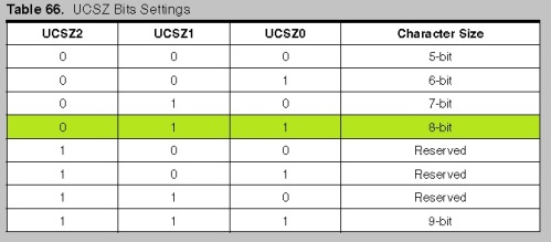
- Bit 2:1 – UCSZ1:0: Character Size
- The UCSZ1:0 bits combined with the UCSZ2 bit in UCSRB sets the number of data bits in a frame (Start bit+ Data bits + Parity Bit (if any)+ Stop bits) for the Receiver and Transmitter use.
2. USART Control and Status Register B –UCSRB
- Bit 4 – RXEN: Receiver Enable
Writing this bit to one enables the USART Receiver. The Receiver will override normal port operation for the RxD pin when enabled. Disabling the Receiver will flush the receive buffer invalidating the FE, DOR, and PE Flags.
- Bit 3 – TXEN: Transmitter Enable
Writing this bit to one enables the USART Transmitter. The Transmitter will override normal port operation for the TxD pin when enabled.
- Bit 2 – UCSZ2: Character Size
The UCSZ2 bits combined with the UCSZ1:0 bit in UCSRC sets the number of data bits in a frame the receiver and transmitter use.
3. USART Control and Status Register A –UCSRA
- Bit 7 – RXC: USART Receive Complete
This flag bit is set when there are unread data in the receive buffer and cleared when the receive buffer is empty (that is, does not contain any unread data).
- Bit 6 – TXC: USART Transmit Complete
This flag bit is set when the entire frame in the transmit Shift Register has been shifted out and there are no new data currently present in the transmit buffer (UDR).
4. USART I/O Data Register – UDR
Register UDR is the buffer for characters sent/received through serial port.
To start sending a data, write it to UDR…
uint8_t data; //initialize the data variable
data = ’k’; //store the data
UDR = data; //now you can send the data
To check the receiving data, after it is sent from transmitter…
uint8_t data; //initialize the data variable
data = UDR ; //this will save the sent data and it will also clear the UDR
5. USART Baud Rate Registers – UBRRL and UBRRH
This is the register UBRR where the baud value needs to be set. Don’t get confused that this is the Baud Rate. The Baud Rate can be calculated using the above formula. See this is a 16-bit register, which has to be initialized separately, considering the memory case of UBRRH (you can’t write it UBRR, unless you have set the URSEL bit).We will see how to access them in a short while.
- Bit 15 – URSEL: Register Select
This bit selects between accessing the UBRRH or the UCSRC Register. It is read as zero when reading UBRRH. The URSEL must be zero when writing the UBRRH.
****************************************
SAMPLE CODES
So, that’s all for the registers. Below you will find the sample codes. This project will have two microcontrollers(TX- ATMEGA32 and RX-ATMEGA8), where Atmega32 will sense the Ground and send the data to Atmega8 glow the LED’s connected to its PORTB (led will glow until the input pin of Atmega 32 senses Gnd).
FOR THE TRANSMITTER (ATMEGA 32)
#include<avr/io.h>
#define USART_BAUDRATE 9600 //FROM THE DATASHEET
#define USART_BAUD_VALUE 416 //F_CPU= 16 MHz
int main()
{
UCSRB |= (1<<TXEN); // Turn on the transmission circuitry
UCSRC |= (1<<URSEL) | (1<<UCSZ0) | (1<<UCSZ1); // Use 8- bit character sizes
//set the baud rate
UCSRC = ~(1<<URSEL);
UBRRH = ( USART_BAUD_VALUE >> 8);
UBRRL = USART_BAUD_VALUE ;
/* Set whole of PORTA as input and turn on LED connected to PORTC when any pin of PORTA senses GND*/
DDRA = 0x00;
PORTA = 0xFF;
while(1)
{ if((PINA & (1<<PA0)) == 0) {UDR = 3 ;}
else if((PINA & (1<<PA0)) ==1) {UDR =1;}
while ((UCSRA & (1<<TXC)) == 0); // Do nothing until transmission complete flag set
}
return 0;
}
FOR THE RECIEVER
#include<avr/io.h>
#define USART_BAUDRATE 9600 // FROM THE DATASHEET
#define USART_BAUD_VALUE 416 //F_CPU= 16 MHz
int main()
{
UCSRB |= (1<<RXEN); // Turn on the transmission circuitry
UCSRC |= (1<<URSEL) | (1<<UCSZ0) | (1<<UCSZ1); // Use 8- bit character sizes
/*set the baud rate */
UCSRC = ~(1<<URSEL);
UBRRH = ( USART_BAUD_VALUE >> 8);
UBRRL = USART_BAUD_VALUE ;
DDRB=0xFF; // initialize PORTB as output for toggling the LED
while(1)
{
/* Do nothing until data have been received and is ready to be read from UDR */
while((UCSRA &(1<<RXC)) ==0);
if(UDR == 3) {PORTB = 0xFF; }
else if(UDR == 1) {PORTB = 0;}
}
return 0;
}
So, with this you are qualified enough to implement USART in your microcontroller.
P.S -Before using USART be sure about the clock frequency in your microcontroller. This is likely to affect your Baud Rate considerably. So, Good Bye!!!! And stay tuned for more tutorials.


Leave a comment